air compressor working diagram
Compression requires Work to be done on the gas Compressor must. Let me explain it with an example.

70 Lovely Single Phase Magnetic Starter Wiring Diagram Air Compressor Pressure Switch Electrical Wiring Diagram Electrical Circuit Diagram
Next you are required to insert the ground wire to provide a ground screw.

. The piston is attached to the crankshaft. Air Compressor Diagram What Is Air Compressor Air Compressor Pdf Air Compressor - Wikipedia Simple Air Compressor Diagram Air Compressor Machine Air Compressor Theory. An Air receiver is a pressure vessel used to store compressed air supplied by the compressor.
In a screw compressor one of the shafts is driving shaft and the other is driven shaft. Surfaces become rough and so this in turn reduces the air pressure within the piping system. Taking air from the top of a compressor means that the amount of moisture.
This process is called the duty cycle. A two-stage air compressor works just like a single-stage compressor in that air is sucked into the cylinder and then trapped and compressed with the piston. Air Compressor 1 Takes in atmospheric air 2 Compresses it and 3 Delivers it to a storage vessel ie.
The inlet and discharge outlet must be designed so that they allow smooth flow of air over the entire system. Working Diagram Construction Function. You should use a moisture filter with a small amount of water in it to trap moisture as its venting from the air compressor.
By slowing the flow of air through a diffuser more kinetic energy is generated. The first element is symbol that indicate electrical component in the circuit. Imagine you are driving your car going smoothly.
This reciprocating compressor consists of an intake valve an exhaust valve a cylinder valves crankshaft and a piston. Most compressors use reciprocating piston technology. The driving shaft is connected to the driven shaft via timing gears which help to match speeds of both the shafts.
Once the storage tank reaches its maximum air pressure the compressor turns off. But instead of then pushing the air into the storage tank the air is pushed to a second smaller piston for a second stroke around 175 PSI before being sent to the storage tank for use with your attached. The pressure switch is connected to the electric motor.
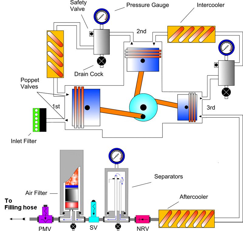
Once you have indicated these you need to first put the red wire in the switch line terminal. Similarly you need to insert the black wire in the switch line terminals as well. Fig shows various parts of three-stage V type reciprocating air compressor with the receiver air tank.
Positive Displacement is the method that most compressors use. Typically an air conditioner is made up of 4 major components. There are other types but the vast majority of air compressors in use today are one of these two types.
A rotary air compressor which is the simplest compressor consists of two rotors with lobes rotating in an air-tight casing that has an inlet and outlet ports. Air compressor working diagram. Updated On May 2022.
To understand the operation of an air compressor let us assume the cycle and indicator diagram for a simple single stage reciprocating air compressor as shown below. The two shafts are enclosed in an airtight casing. Reduce the moisture within your air compressor piping diagrams by changing the supply inlet.
In order to compress air the internal components of a compressor must move or change position to mechanically force the air through the chamber where it is compressed and stored until use. Electric high-speed motors are typically used for these kinds of compressors. The compressor draws in air and creates a vacuum to reduce its volume.
Because these sudden sharp angles slow down the flow of air and as a result the pressure also drops. The line terminals are specified for black as well as red wires. The discharge pipe should be the same size as the compressor outlet.
When working on your air compressor hose diagram you should always avoid sharp angles. Content025 Overview about the different types of air compressors052 Working principle of a si. The core of how air compressors work is boiled down to two methods of air displacement.
As the piston moves in a downward direction then the air pressure in the compressor cylinder drops lower than the pressure of. The vacuum pushes the air out of the chamber and into its storage tank. Multiple air users should not be connected to the same drop each drop should.
List of Top Rated Air Compressor Working Diagram from thousands of customer reviews feedback. The reciprocating compressors and other intermittent discharge compressors will require an air receiver to discharge compressed air in the tank Ibr storage and further use. This tutorial describes the function of an air compressor.
The driving shaft is powered by an electric motor generally. Energy used by an industrial air compressor is converted into heat. Click the image to enlarge The simple reciprocating air compressor has a piston which reciprocates inside the cylinder wall and cylinder head.
The recommended moisture content in the air after its compressed should be between 25 and 35. In many cases a properly designed heat recovery unit can recover anywhere from 50 to 90 percent of this available thermal energy and put it to useful work heating air or water. Air Compressors COMPRESSOR A device which takes a definite quantity of fluid usually gas and most often air and deliver it at a required pressure.
Air Compressor Anatomy 101. Compression condensation expansion and evaporation. The safety valve opens when the pressure in the air tank exceeds the set safe pressure.
This has pretty detrimental effects on piping air to the air tool. A reciprocating compressor is used in gas pipelines chemical plants air conditioning and refrigeration plants. Net potential is 40 to 84 recovery.
In general they consist of an air pump a motor or engine and a. An air conditioner goes through 4 processes. Compressor heat exchanger fan and expansion valve.
Piston air compressor works more likely a car piston motors working. Centrifugal or radial compressors work by bringing air into the center through a rotating impeller which is then pushed forward through centrifugal or outward force. To understand the operation of an air compressor let us assume the cycle and indicator diagram for a simple single stage reciprocating air compressor as shown below.
The first airdrop should be about 50 ft away from the compressor for optimal performance. AC Working Principle in Diagram. When the desired pressure in the air tank is reached it stops the motor and hence the compressor.
Here we we have breakdown drawings and diagrams of Piston air compressors reciprocating aka Recip as well as for Rotary Screw air compressors. The single-acting air compressor working principle is very simple that is given below in detail. The excess moisture will be absorbed by the filter and you should empty the catch basin regularly.
This helps because water is heavier than air and drops to the bottom of the tank. Specific refrigerants are needed as the working fluid in the refrigeration cycle.

Wiring Diagram For Firestone Level Command Ii On Board Compressor Kit For Air Bag Suspensions Air Ride Air Bag Firestone Air Bags

How Do Air Compressors Work Air Compressor Tank Air Compressor Repair Compressor
High Pressure Breathing Air Compressor Filtration System Design Author Stephen E Burton Bsc Hons C Eng Miet Emai Compressor Systems Theory Air Compressor

Compressor Working Principle Crosshead Design Reciprocating Compressor Compressor Compressors

Air Conditioner Compressor Wiring Diagram Before You Call A Ac Repair Man Air Conditioner Capacitor Refrigeration And Air Conditioning Refrigerator Compressor

Compressor Working Principle Trunk Design Reciprocating Compressor Compressor Compressed Air

Pin On Compressed Air Equipment And Piping System

Pin On The Abc S Of Commercial Hvac Terminology
Air Conditioner C S R Wiring Diagram Compressor Start Full Wiring Fully4world Refrigeration And Air Conditioning Hvac Air Conditioning Hvac Training

Awesome Refrigerator Compressor Relay Wiring Diagram Electrical Wiring Diagram Compressor Electrical Circuit Diagram

C S R Compressor Wiring Diagram With Voltage Type Relay Fully4world 4 961 Total Views 1 Views Today Compressor Diagram Refrigeration And Air Conditioning

The Science Behind Refrigeration Scroll Compressor Injection Moulding Compressor

Air Compressors Market Analysis By Top Players 2020 Frank Compressors Compressed Air Hvac Services Compressor

Pin On Air Compressors

Learn About The Operation Of An Air Compressor With The Help Of Diagrams For Every Stroke Of The Piston Also Compare Your U Air Compressor Compressor Operator

Pin By Student On Cooling Air Conditioner Maintenance Refrigeration And Air Conditioning Hvac Air Conditioning

Pin On Garage Workshop

Air Conditioner C S R Wiring Diagram Compressor Start Full Wiring Fully4world Refrigeration And Air Conditioning Hvac Air Conditioning Hvac Training

Air Compressor Pumps Industrial Reciprocating Usa Made Saylor Beall Refrigeration And Air Conditioning Air Compressor Automotive Repair